


ANTI-LEAD BALL RESPONSE
Home > Data Room > Anti-lead ball response
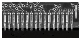
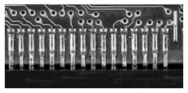
 Lead Ball Test Image Data Lead Ball Test Image Data
As we use pb free solder, we are having difficulty responding to solder and lead ball quality problems. Therefore, I would like to explain the cause of lead ball occurrence and countermeasures in the hope that it will be a little helpful in responding to it.
Classification according to cause of lead ball
Lead balls in wire solder soldering can be divided into two main types depending on the occurrence factors. One is a lead ball caused by a Flux gas explosion inside the wire solder due to heat supply, and the other is when lead melted by the iron tip during soldering cannot be recovered by the iron tip due to several factors. The countermeasures will be different depending on the causes above. In the case of the former lead ball, the higher the temperature and the higher the Flux content, the higher the frequency of occurrence of the lead ball, and there is a big difference for each lead maker. It is usually a solder ball found outside the solder land, and the latter is characterized by the solder ball remaining around the solder land and falling off the impact easily.
Analysis of Lead Ball Occurrence
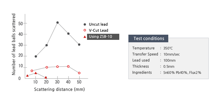
For test pb free, N company pb free of higher quality than general products in terms of high temperature response and lead ball reliability was used, and during the test
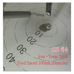
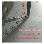
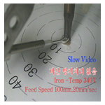
Since the occurrence of lead balls was rarely observed due to the use of lead ball prevention devices, the Flux scattering phenomenon was evaluated by equating it with the occurrence of lead balls. [A comparative analysis of the occurrence of pb free lead balls when not using a lead ball preventing device] Test conditions: Temperature: 340℃, lead used: (Sn96.5 Ag3 Cu0.5) 1.0 Ø P4, supply: 100 mm, supply rate: 20 mm/sec
Anti-lead ball measures1. Lead Ball by Flux Gas Explosion 1) Please set it to the optimum low appropriate temperature.
(1) If there is no problem with the heat source of the base material, soldering work can be performed from 260℃ in the case of lead-free soldering. (2) If there is no problem with the heat source of the base material and parts, use the first preheating time at a temperature of about 340-380°C for the ground pattern and the part that requires the heat source, secure the heat source, and then perform the second soldering operation. * The supply speed of the primary lead is low (3~7mm/sec) and please respond to the heat supply of the lead tip during initial supply. (3) Please set the supply speed of the second supply lead to low speed (2~7mm/sec) and create conditions so that the supply of Flux can be made by the end of soldering. * In particular, when using small points and small amounts of lead-free lead, the condition in paragraph (3) is a very important condition for securing lead-free solder quality. * You can understand that the supply conditions of Flux are maintained in proportion to the lead-free soldering time. * Simultaneously operating the supply of primary lead when the cylinder is lowered is one of the techniques that maintains the oxidation of lead and the activity of Flux. 2) Please make sure that the lead passed through the ZSB Feeder is formed to eject the flux gas.
 * If you do not adopt the ZSB Feeder, it is recommended to do so.
* In the case of recent Apolloobotics soldering robots, all types of lead ball prevention devices are employed and released. * There is also a solder ball prevention device for hand soldering. (See product introduction ZSB Feeder.) * When using thick thread lead with a thickness of 1.2 or more, a lead preheating device is employed. 3) Please set the lead supply speed within 5~20mm/sec. Please be careful when selecting lead because there is a big difference in the generation of lead balls depending on the manufacturer and type of lead. 4) In the case of lead with a high frequency of lead ball occurrence, set the supply speed of lead to a low-speed supply of about 5-7mm/sec. 5) Set the supply position of lead to the tip of the iron tip, and if the supply position can be changed during the second lead supply, set the lead to melt to the land part. This is a response to prevent the occurrence of lead balls due to heat supply. 6) And in the case of lead-free, wettability and spreadability are very bad compared to conventional lead, so setting the supply position of lead-free is also important, so please ensure that lead-free is supplied exactly where to join. 2. lead ball around the soldering area 1) Please review the specifications of InduTip.
- If you use a two-sided iron tip with lead on the side and back, please use a black chrome plated part removed for about 1 mm. - Please select the size of the iron tip as a size larger than 0.5mm or the same size based on the soldering land. 2) Shame the cylinder rise speed at 20 to 40 mm/sec. |
||||||||||||||||||

|
